
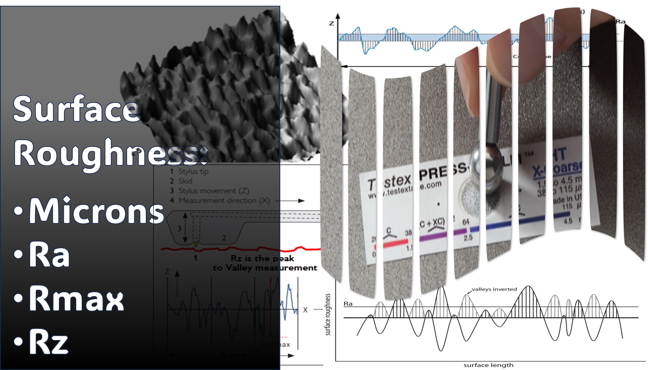
1. Surface Profile: The Foundation of Every Protective Coating
Surface preparation is widely recognized by NACE, AMPP, and ISO standards as contributing to over 75% of premature coating failures. Even the most advanced polysiloxane, epoxy mastic, or polyurethane systems will fail catastrophically through blistering, adhesive disbondment, or underfilm corrosion if the underlying anchor profile is compromised.
When abrasive blasting steel to ISO 8501-1 Sa 2½ (Near-White Metal) or SSPC-SP 10 / NACE No. 2, the kinetic impact of high-velocity abrasive particles creates a three-dimensional topography of peaks and valleys known as the anchor pattern or surface profile. However, characterizing this profile using only a single roughness parameter often leads to misleading specification compliance and catastrophic in-service degradation.
2. Deconstructing Roughness Parameters: Ra, Rm, and Rz
In mechanical engineering and industrial surface preparation, multiple parameters describe surface roughness. Understanding their distinct mathematical definitions is critical for coating QA/QC specialists:
| Parameter | Standard Definition | Relevance to Protective Coatings |
|---|---|---|
| Ra | Arithmetical mean deviation of the assessed profile | Useful for machined components; extremely dangerous for blast-cleaned steel because high peaks and shallow valleys can average out identically. |
| Rz | Mean peak-to-valley height across consecutive sampling lengths | The primary parameter specified in protective coating data sheets (typically 50–75 µm). Governs mechanical grip and primer wet-out. |
| Rm (Ry / Rmax) | Maximum individual peak-to-valley height within the evaluation length | Crucial for detecting rogue high peaks that protrude through the primer coat, creating early pinpoint rust nucleation points. |
"Two blasted steel plates can exhibit an identical Ra of 12 µm, yet one plate may have an Rz of 50 µm with uniform dense peaks, while the other features an Rz of 110 µm with sharp jagged peaks that easily pierce a 60 µm primer coat."
3. The Practical Hazards of Profile Deviations
A. Insufficient Surface Profile (< 35 µm)
When the profile height is too low, the available mechanical anchor area is drastically diminished. Liquid coating binders cannot physically interlock with the steel substrate. Under thermal cycling, cyclic pressure loads, or structural flexure, the system experiences adhesive delamination at the steel-primer interface.
B. Excessive Surface Profile (> 100 µm)
Conversely, a profile that exceeds project specifications creates two severe field issues:
- Pinpoint Rusting (Peak Protrusion): If the dry film thickness (DFT) of the primer is specified at 60–75 µm, isolated sharp steel peaks (Rm) exceeding 100 µm remain uncoated or covered only by a minuscule film, causing rapid atmospheric rust spotting within weeks of handover.
- Dead Volume Loss: The volume of paint required to fill the microscopic valleys below the peaks before establishing a measurable dry film over the peaks is termed dead volume. Excessive profile depth consumes up to 30–40% more primer than calculated theoretically.
For steel blasted with angular grit, the volume of paint lost in the dead volume is approximately Dead Volume = 0.5 × (Rz in µm) / 1000 litres per square meter. For a 75 µm profile, expect roughly 0.0375 L/m² of primer to reside purely in the valleys below the peaks!
4. Field Measurement Methodologies: ISO vs. ASTM
Coating inspectors have three main standard methods to evaluate blast profile on site:
- ASTM D4417 Method C / ISO 8503-5 (Replica Tape): Using Testex Press-O-Film (Coarse and X-Coarse) with a calibrated spring micrometer. It measures the true peak-to-valley height (Rz equivalent) and provides a physical permanent record for quality documentation.
- ASTM D4417 Method B (Surface Profile Gauge): A digital needle-point depth micrometer with a 60° conical tip. Highly mobile and rapid, requiring a minimum of 10 individual readings per location to produce a statistically valid average.
- ISO 8503-1 / 8503-2 (Surface Profile Comparators): Visual and tactile reference discs (Grit or Shot comparator) divided into four segments calibrated from Fine (G) to Very Coarse (G). Best utilized for rapid visual calibration before instrument verification.
5. Field Inspection QA/QC Checklist
To guarantee that surface profile parameters satisfy client engineering specifications, follow this operational protocol:
- Verify abrasive particle size distribution (PSD) and ensure the working mix is free from oil and moisture (perform the ASTM D4940 water-soluble conductivity test and ASTM D7393 vial oil test).
- Measure profile across at least three distinct 150 × 150 mm inspection locations per 100 square meters of blasted steel.
- Check environmental conditions before blasting: steel temperature must be a minimum of 3°C (5°F) above the dew point, and relative humidity must be below 85%.
- Record ambient conditions, abrasive batch numbers, comparator grading, and exact micrometer readings directly into the daily inspection report (DIR).